Raspberry PI Pico: The Wonder Board for IoT Applications
This hands-on tutorial with a Raspberry Pi Pico microcontroller board will get you started on your IoT journey. The Internet of Things (IoT) touches every aspect of our lives today. We can keep an eye on our home from hundreds of miles away through smart security cameras, while home assistant devices like Alexa obediently follow our commands to control our entire home. Every corner of our home or workplace has these tiny but powerful intelligent devices that create a whole automated system to provide a comfortable life.
Recent advances in open hardware and software standards-based systems have helped replace pricey and complicated embedded systems. The Raspberry Pi (RPI) Foundation has designed many general-purpose single board, low power and cost-effective hardware systems in the last few years to help create powerful IoT systems with a fraction of the effort and cost involved earlier. Millions of intelligent devices around the world are already using RPI hardware for modern IoT usage. So let’s jump onto this rocket ship of IoT too.
Raspberry PI Pico Board Overview

Raspberry PI Pico 1 / 2 are generation 1 and 2 families of microcontroller boards with system-on-chip (SoC) based on ARM dual-core RP 20240/2350 processors. Both families have boards with wireless LAN and Bluetooth connectivity too. You should be able to buy a Pico 1 board from a Raspberry Pi reseller in your country at a price of roughly ₹300 to ₹400 through the Raspberry Pi official website.
Remember that when you buy a board through reseller websites, if you see a letter H added after Pico 1 / 2 it means the header is soldered on the board. The board with a header could be inserted at various places to control and interact with more external hardware components. And when you see the letter W appended after your Pico 1 / 2 series it indicates boards with wireless capabilities. The Pico 2 family is just an upgrade over Pico 1, with roughly double the RAM and faster cores, etc.
Setting Up the Raspberry PI Pico Board
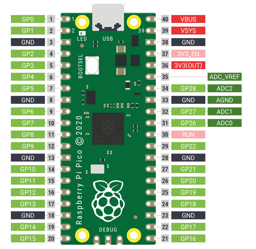
We’ll use the Pico 1 series board in this article to get started with the necessary fundamentals to quickly embark on our IoT journey. You don’t need any external electronic component, except a micro USB to USB cable to experiment with the Pico code snippets given in this section. Your Pico board should look like what’s shown in Figure 1 with important components like a USB port to program/power, onboard LED, BOOTSEL button, and a big black microcontroller chip in the middle clearly visible on it.
Now let’s set up the software to program our Pico 1 board. First, download the necessary firmware for Pico from the MicroPython download page link provided in the References section at the end of this article. Next, connect the USB cable to your computer, and press and hold the BOOTSEL button while inserting the cable into the micro USB port of the Pico board. You should see the Pico board mounted as a USB device in your computer. Just copy the downloaded UF2 firmware to the mounted Pico drive. The UF2 file will disappear from the mounted Pico drive once programming of the new firmware is complete. Now your Pico device will reset automatically and be ready for use.
Programming IoT Activities with Thonny Python IDE

Finally, we just need a Thonny Python IDE to interact with your Pico board, and program that for various IoT activities. Thonny is intelligent enough to detect your Pico board is connected and ready to program. You can also configure Thonny through the ‘Configure interpreter’ menu item in the right bottom side of the IDE.
The Pico board has an LED connected to its programmable input-output pin 25. The logic of the MicroPython code shown above is simple: we set the GPIO pin 25 as an output pin, make the voltage high to ‘on’ the onboard LED and ‘off’ it after a delay to witness the LED glowing up. Let’s make the project more interesting by introducing a loop that will make the onboard LED blink continuously.
Exploring More IoT Capabilities of Raspberry PI Pico
Wouldn’t it be nice to see the onboard LED blink in a fading up/down manner, for a change? The Pico board has pulse width modulation functionality for that. The Pico board has analog-to-digital converters to measure analog signals and convert them to digital numbers to hand over to the microcontroller for processing in multiple ways.
Last but not least, you can program the Pico board to run your code every time when powered up. Once you finalize your MicroPython code after testing, just hit the Save button in your Thonny IDE and save your code as main.py. The low cost, power-efficient, and versatile Raspberry Pi Pico boards have really opened the way for everyone to begin their IoT journey.
We have just scratched the surface of the great IoT capabilities provided by the RPI Pico board to get you quickly started with it. Do explore the vast array of real-world projects available freely on the internet, as there is already a great open-source ecosystem around it for you to create some breathtaking IoT systems.